how to add a light fixture to an existing circuit diagram
Wiring Diagrams to Add a New Light Fixture
Check local regulations for restrictions and permit requirements before beginning electrical work. Per the NEC, the number of conductors allowed in a box are limited depending on box size and wire gauge. Calculate total conductors allowed in a box before adding new wiring, etc. The user of this information is responsible for following all applicable regulations and best practices when performing electrical work. If the user is unable to perform electrical work themselves, a qualified electrician should be consulted. How to Read These Diagrams
This page contains wiring diagrams for adding a new light fixture to an existing circuit. There are diagrams for adding lights to a ceiling fixture you already have and for using an existing wall outlet as the source for a new switch and light. Different wiring arrangements are included to allow for either the light or the switch to come first in the circuit. Also, find a diagram for adding a light from a switched receptacle you already have to include the fixture when you turn on the room light.
Wiring a New Switch and Light from an Outlet
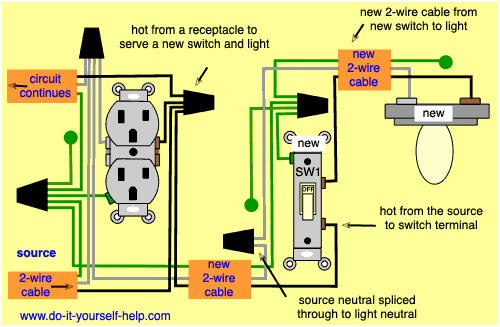
In this diagram power is taken from an existing wall outlet for a new switch and light fixture. The switch comes first in the new part of the circuit and new 2-wire cable is run to it from the outlet. From the switch, new 2-wire cable is run to the new light location.
The neutral for the new light is taken from the receptacle and spliced to the new white wire and to a pigtail that connects back to the receptacle. Likewise, the source hot is removed from the receptacle and spliced to the new black wire and a pigtail connecting back to the hot terminal on the outlet.
At the switch, the black wire from the outlet is connected to one terminal on the switch and the black wire running to the new light is connected to the other. The white wire from the receptacle is spliced to the white wire going to the light, it doesn't connect to the switch in this diagram. At the light, the black wire connects to the hot terminal on the fixture and the white connects to the neutral terminal.
Wiring a Switch and Light in a Double Outlet Box
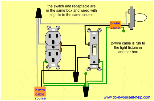
This diagram is similar to the one above, but both the receptacle and the new switch are in the same box at the end of a household circuit. When adding a new switch like this, a new double-gang box will have to be installed if a single outlet is used for the source. If there are two outlets in a box, one can be removed and a switch installed in its place to control a new light.
In this wiring, the hot source wire is taken from the receptacle and spliced to two pigtail wires. One pigtail is connected to the a switch terminal and the other connects back to the hot on the receptacle. The other switch terminal is connected to the black wire running to the new light. The source neutral is taken from the outlet and spliced with a pigtail back to the outlet neutral and to the white wire running to the light neutral terminal.
Wiring a New Light and Switch Loop from an Outlet
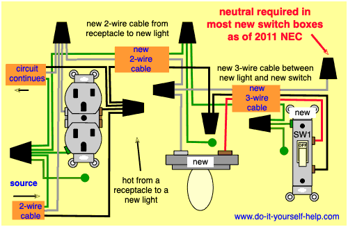
This drawing shows the wiring for adding a new light and switch with the fixture coming first in the circuit. New cable is run from the receptacle to the new fixture location and a switch loop cable is run from there to the new switch location. The switch loop is a 3-wire cable to comply with NEC requirements of a neutral in all new switch boxes.
At the receptacle, the always-hot wire is spliced to the black wire on the light fixture cable, and to a pigtail that connects back to the hot terminal on the wall outlet. At the light fixture box, the black wire is spliced with the black wire running to the switch. At the switch, the black wire is connected to the new switch.
Back at the source, the neutral wire is spliced to the white wire running to the light and to a pigtail connecting back to the receptacle neutral terminal. At the fixture, the white connects to the neutral terminal on the light. The red wire from the switch loop is connected to the hot terminal on the light and at the other end to the new switch. The white wire is capped with a wire nut in the new switch box.
Wiring a New Light from a Switched Outlet
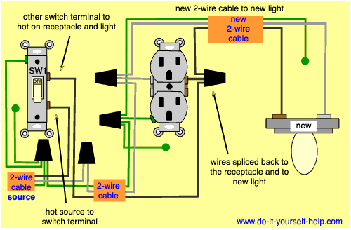
The wiring in this diagram is for adding a new light fixture to a switched outlet, i.e. one that is hot only when a switch is on. These are commonly used to turn a table or floor lamp on and off from a wall switch.
New 2-wire cable is run from the receptacle to the new light fixture. At the receptacle, the wires are removed and each one is spliced to the new cable and back to the receptacle with a pigtail splice. At the light fixture box, the black wire connects to the hot terminal and the white connects to the neutral terminal.
Wiring to Add New Lights from an Existing Fixture
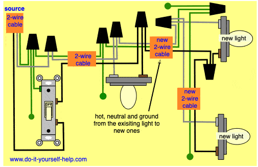
In this diagram, two new light fixtures are added to one that already exists. New 2-wire cable is run from the existing light fixture box to the first new box. From there, new 2-wire cable is run to the second new light box. If desired, more lights can be added after that by running new cable to each new light box.
At the existing light, the hot and neutral wires are removed from the fixture terminals and spliced to the new cable wires running to the first new light. A pigtail is also added to the splice to allow for reconnecting the existing light back into the circuit. At the first new light, the wires are spliced to the new cable running to the next light and to a pigtail to connect the first new light. If you want to add more lights after the second new one in this diagram, they can be spliced into the circuit in the same way.
Wiring a New Light from an Existing Switch
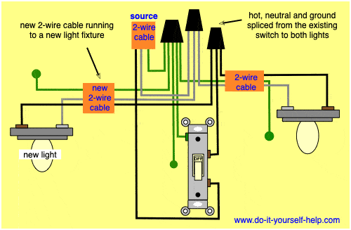
This wiring illustrates how to add a new light fixture from an existing switch instead of from the light fixture. In this circuit, the neutral and ground wires running to the new light are spliced in the switch box with the wires running to the existing light. The black wire running to the light is taken from the switch and spliced with: a pigtail back to the switch, the black wire running to the new light, and the black wire running to the existing light. The switch will now control both light fixtures in the circuit.
Wiring Diagram for a New Switch and Light
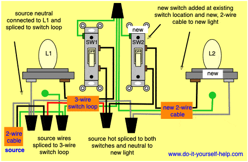
In this diagram, a new switch and light are added to an already existing light switch. The source for this circuit is at an already existing light fixture and a 3-wire switch loop run from there, to the switch box. This 3-wire switch loop satisfies the NEC requirement of a neutral in the switch box.
At the switch location, a new double-gang box is installed to allow room for a second switch to control the new light. This arrangement will allow for controlling each light separately.
The hot from the switch loop is spliced with a pigtail to both switches. New 2-wire cable is run from the switch box to the new light fixture location. The neutral wire from the switch loop is spliced to the new white wire. The black wire is connected to the other terminal on the new switch and to the hot terminal on the new light.
- Light Switch Wiring Diagrams
- Switched Outlet Wiring Diagrams
- Receptacle Outlet Wiring Diagrams
- Double-Gang Box Diagrams
- Wiring for Multiple Outlet
- 3 Way Switch Wiring Diagrams
- 4 Way Switch Wiring Diagrams
- 3 Way Diagrams for Multiple Lights
- New Light Wiring Diagrams
- New Outlet Wiring Diagrams
- GFCI Outlet Wiring Diagrams
- GFCI Switch Outlet Wiring Diagrams
- Circuit Breaker Wiring Diagrams
- Ceiling Fan Wiring Diagrams
- Lamp Switch Wiring Diagrams
- Doorbell Wiring Diagrams
- Adding Wiring Behind Baseboards
- Running New Electrical Cable
- How to Splice Electrical Wires
- How to Wire Outlets and Switches
- Framing to Add a Ceiling Fan
- Calculating Circuit Load
- Electrical Tools and Materials Guide
how to add a light fixture to an existing circuit diagram
Source: https://www.do-it-yourself-help.com/adding-new-light-wiring-diagrams.html
Posted by: livingstonantley.blogspot.com

0 Response to "how to add a light fixture to an existing circuit diagram"
Post a Comment